The Difference Between Traditional and Resettable Fuses
Fuses can be categorized as traditional one-time devices or resettable PTC fuses that can continue to protect circuits without the need for replacement.
Download PDFWhen is a Fuse Not a Fuse?
The electronic interfaces in today’s consumer electronic products provide higher performance and can supply higher currents than ever before. However, these higher currents can lead to blown fuses which are difficult if not impossible to replace. To avoid the need to replace fuses or entire circuits, resettable PTC fuses may be used. PTC fuses reset themselves and can continue to protect circuits without the need for replacement, reducing down-time and extending the life of the application.
What is a Traditional Fuse?
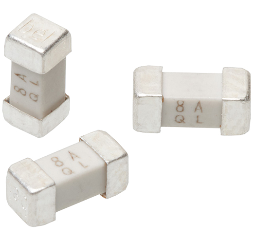
A traditional fuse consists of a piece of wire or other conductive link with a known current-carrying capacity placed in series with an electric circuit. The fuse functions solely as a safety device that is designed to melt and permanently interrupt further current flow. By operating, fuses protect circuits from damage caused by overload or short circuit current, thereby preventing overheating and even fire if a fault condition should occur.
Depending on the circuit being protected, fuses can be rated from a few milliamps in small consumer electronic products to hundreds of amps in industrial applications. Current rating alone is not sufficient to specify a fuse for a particular application; fuses are also rated for voltage, AC and/or DC. The voltage rating is a maximum and cannot be exceeded. Once the fuse operates, there is no chance of arcing across the fuse. Depending on whether the load is resistive or reactive, fuses are available that are designed to blow “fast” in the event of a current overload, or designed to allow a brief overload for a defined short time period before blowing, often called “time delay” or “slow” fuses.
How Do Circuit Parameters Affect Fuse Selection?
Fuses also need to be selected according to circuit parameters. Certain semiconductor circuits require a fuse to clear very quickly to avoid possible significant/expensive component damage. Conversely, highly inductive or capacitive circuits such as power supplies may generate brief inrush surges at “power-up”, where the circuit current is well above a fuse’s rating for a very short time. Circuits like this require a “Time Lag” or “Slow Blow” type fuse to allow it to ride out these brief but normal surges without causing what’s known as “nuisance clearing”. This is also true for motor and transformer in-rush currents.
One thing all fuses have in common is that they are “one-time” devices. When any conventional fuse is forced to clear, installing an exact replacement after repairing the underlying fault is the only way to repower the protected circuit. But as electronic systems continue to shrink and evolve, the single use nature of the fuse has come under increasing pressure.
Do Blown Fuses Need to Be Replaced?
Prior to the advent of miniaturization and the rise of microcircuits, equipment fuses were mechanically held by holders or clips. A repair consisted of determining which fuse had cleared; locating/accessing the blown fuse; diagnosing the underlying problem and then finding a replacement fuse with the proper ratings and clearing behavior. Today, most electronics and small appliances are too densely designed to accommodate older style tubular fuses and currently use SMT types soldered in place, and so are not user-serviceable. The act of simply replacing a fuse has now morphed into changing a circuit card or returning the device/appliance for factory rework. Most consumer electronic products are not designed to give access to an internal replaceable fuse, as product designers go out of their way to prevent access inside, with product labels warning “No User Serviceable Parts Inside”.
The electronic interfaces between today’s consumer electronic products provide higher performance and can supply higher currents than ever before, as with the latest version of the USB interface, for example. Interface cables and connectors grow ever smaller and are more easily damaged by careless users who plug and play at will. The risk of a faulty or incompatible peripheral device being plugged into and damaging a host product is concerning. No manufacturer wants product returns, especially under warranty, and some type of protection component like a fuse is ideally still needed, but maybe not a traditional fuse. Given the path things have taken, wouldn’t it be nice to have a protective “fuse” that would auto-reset once a fault was removed? Bel’s PTC devices do just that!
Discover Bel's Resettable PTC Fuses
Learn MoreWhat is a PTC Fuse?
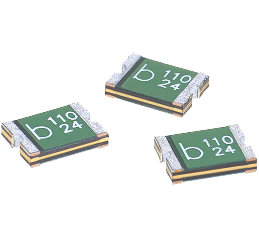
A Bel PTC fuse is similar in operation to a positive temperature coefficient (PTC) thermistor; that is, a temperature dependent resistor whose resistance increases with increasing temperature. However, a Bel PTC self-resetting protector differs from a thermistor in that it is not simply a passive measuring element but rather is designed to carry circuit current and thus will self-heat due to the resistance of its active core; a carbon particle infused polymer. A PTC fuse increases its resistance rapidly in response to an overcurrent, short circuit or overtemperature situation to limit the current flow. The PTC fuse is not permanently destroyed by the fusing event and will reset after power to the circuit is removed, the fault cleared and power reapplied. The reset capability allows electronic products to be protected by a PTC but eliminates the requirement for service personnel to ever physically replace it like a traditional fuse.
In construction, a Bel PTC consists of a block of polymer material containing conductive filler bonded between two conductive plates. Current passes between them through thousands of random, carbon chain pathways formed by the physical contact of random, adjacent carbon particles. While the current through the PTC fuse is below its IHOLD rating and its temperature below 100°C, conductive pathways through the device conduct current with a low resistance below its R1 MAX rating. As the PTC fuse’s temperature approaches 130°C, due to an increase in the ambient temperature or the current exceeding its ITRIP rating, volumetric expansion of the filled polymer block breaks apart the majority of conductive pathways, leading to a sharp increase in the PTC fuse's resistance by several orders of magnitude.
How Do You Reset PTC Fuses?
In the tripped state, current flow is limited by the new much higher resistance but there is still enough leakage current through the PTC fuse to allow internal self-heating to continue to hold the PTC fuse in the tripped state until power is completely removed. Once power is removed, the PTC’s core cools and contracts, allowing the conductive chains to reform and return the device to the low resistance state.
Note that the temperature rise required to initiate a trip event can stem from internal heating (i.e. overcurrent) or heat from an adjacent, external source (i.e. an overheated motor housing). PTCs will respond equally well to either condition, making them versatile protectors as well as providing their auto-reset feature.
A Bel PTC data sheet specifies the typical power, Pd, needed to sustain a PTC in the tripped state in 23°C still air. Since power (P) = current (I) * voltage (V) and by Ohm’s law voltage (V) = current (I) * resistance (R), we have P = V^2/R, and therefore the approximate resistance of a tripped PTC is R = V^2/Pd where Pd is the tripped dissipation. Since the PTC acts to maintain a constant internal temperature, its apparent tripped resistance will change depending on applied voltage.
Example 1: 1W PTC on 60V supply. R_tripped = 60^2/1 = 3600 ohms.
Example 2: Same 1W PTC on 12V supply. R_tripped = 12^2/1 = 144 ohms.
The figure given for typical power is only “typical” because any physical factors that affect heat loss, such as cooling, will alter the power dissipation needed by the PTC to maintain its internal temperature. In short, PTCs do not exhibit a constant quantifiable tripped resistance.
It is important to note this key difference between a traditional fuse and a PTC fuse, specifically that the load circuit is not completely isolated during a fault and that a high resistance leakage path still exists through it. A typical application for PTCs is in safety circuits as limiting devices to provide overcurrent protection, such as covered by UL’s UL1434 and TUV’s EN 60738-1-1. See device data sheets for more information on safety agency approvals per device.
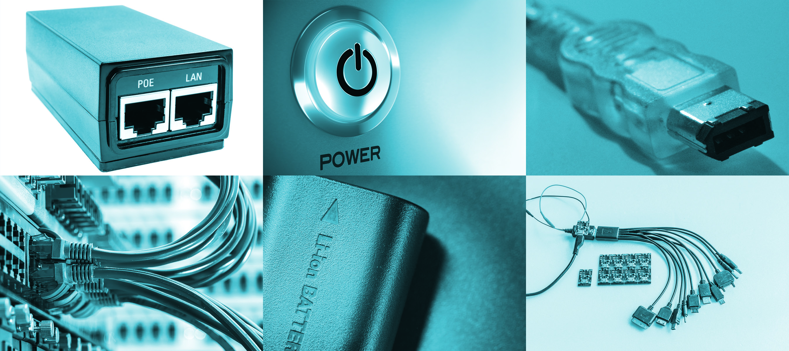
Apart from USB interfaces, other applications that benefit from PTC protection include:
- IEEE 1394 Firewire
- Power over Ethernet (PoE)
- Lithium-Ion Battery Packs
- Battery Charger Circuits
- PC Peripherals
- Disk Drive Interface
- Transformer
- Telecom Line Interface
- Motors
- Power Supplies
- Heaters
- Toys
Resettable PTC Fuses
Bel resettable PTCs are designed for use in applications from -40°C to +85°C and available in traditional radial leaded packages and surface mount (SMD) chip packages ranging from 0603 to 2920 size.
The 0ZCM series of 0603 SMD devices offers very small size suited to the highest density printed circuit board (PCB) applications. The typical power dissipation Pd for these devices is 0.5 W. Individual devices with specified operating (hold) current ranging from 50 mA to 200 mA and corresponding trip current from 150 milliamps to 450 mA respectively are available. Depending on actual selected device and operating conditions this series offers fast sub second (0.1 sec Max) trip time for currents in the range 500 mA to 2 A and Max operating voltage in the range 9 to 15 V.
By comparison the larger 0ZCF series of 2920 SMD devices suit higher power PCB applications. The typical power dissipation Pd for these devices is 1.5 W. Individual devices with specified operating (hold) current ranging from 300 mA to 3 A and corresponding trip currents from 600 mA to 5.2 A respectively are available. Depending on actual selected device and operating conditions this series offers maximum operating voltages from 6 to 60 V. Radial leaded PTCs are offered in a number of series with 5.1 mm and 10.2 mm lead spacing and can support much higher operating voltage and current. These devices are suitable for line voltage power supply, transformer and appliance applications.
The 0ZRM series supports a maximum operating voltage of 120 VAC/VDC with a maximum of 135 VAC/VDC. Individual devices with specified operating (hold) current ranging from 100 mA to 3.75 A and corresponding trip current from 200 mA to 7.5 A respectively are available.
The 0ZRE series supports a maximum operating voltage of 240 VAC/VDC with a maximum voltage of 265 VAC/VDC. Individual devices with specified operating (hold) current ranging from 50 mA to 2 A and corresponding trip current from 120 mA to 4 A respectively are available.
The 0ZRA series supports very high operating (hold) current ranging up to 14 A and corresponding trip current up to 23.8 A.
Limitations of PTC Fuses
Polymer PTC devices are only intended for protection against occasional overcurrent/overtemperature fault conditions and may not be suitable for applications where repeated and/or prolonged fault conditions are anticipated.
PTC devices may not be suitable for use in circuits with large inductance as the PTC trip can generate large voltage spikes greater than the PTC-rated voltage.