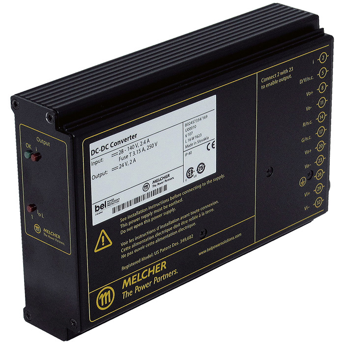

Converters Oscillating while Testing Surge Immunity
Clarification & recommendations for DC-DC converters for railway applications oscillating when being qualified against surge immunity requirements.
Download PDFThe inductance inside a decoupling network between a dc power source and the input capacitance of a DC-DC converter can cause oscillations that may result in start-up failures and equipment damage. The equipment used during IEC 61000-4-5 surge testing is especially likely to cause oscillations if mitigation measures are not taken. Below explores the cause of the oscillations and what may be done to avoid them.
Surge Immunity Test Requirements (IEC 61000-4-5)
Test Objective
- The objective of this test is to evaluate the performance of the Equipment Under Test (EUT) under high-energy disturbances (Surge pulses) on the power and interconnection lines. These disturbances may be caused by over-voltages from switching and lightning transients
- Surge is usually applied to AC (or DC) power input ports, but in some standards, it is also to be applied to signal ports.
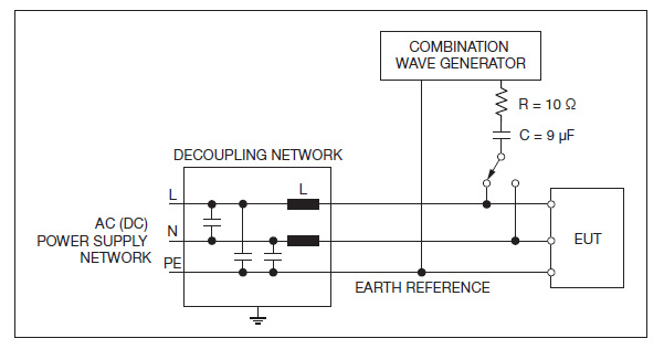
- The surge pulses are usually coupled directly to the signals via source impedance (e.g. Resistance of 10 Ω, Capacitance of 9 µF in series).
- The coupling - decoupling network (CDN) is usually contained inside an immunity test system and helps to protect the power supply or auxiliary equipment during surge testing.
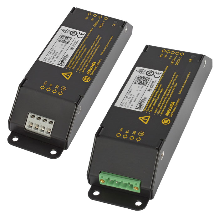
Engineered Solutions for Railway Applications
Bel's Rail CapabilitiesProblem Definition
The problem is related to the presence of an inductance used inside the CDN to decouple DC power source from DC/DC converter with combination of a capacitance of converter. The higher inductance is used in the CDN, the higher probability of oscillations can be expected. On contrary, with higher input capacitance of converter, oscillations are less probable.
Once EUT is connected through the CDN, currently designed converters may not power up or can oscillate. In some cases, these oscillations may cause EUT is being damaged.
Large storage capacitors formerly used in input circuits of older converters to store the energy between conduction cycles are in recent designs eliminated or reduced dramatically in order to meet other important converter characteristics (inrush current or input discharge timing requirements).
Considerations for Remediation
Increasing the input voltage of DC source
The higher input voltage is applied, the lower probability of oscillations can be expected. Also, it is important to make sure that the DC source voltage is adjusted high enough to compensate losses on CDN and input wires (e.g. with a 300 W DC/DC converter power by 24 V and CDN having series impedance of 0.5 Ω, voltage drop on the CDN will be about 7 V). Also, Railway standard EN 50121-3-2 defines, that surge test is to be performed at maximum input operating voltage (e.g. to test at 137.5 V for applications with 110 V battery voltage).
Decreasing output current of load
With lower output power, the input current drawn from the source is lower – with adequately low loading, oscillations would disappear.
Using a CDN with higher current rating
These have typically lower decoupling inductance and lower series resistance which lead to lower probability of oscillations at given line and load conditions. Generic surge immunity requirements defined in standard IEC 61000-4-5 do not specify parameters for CDN inductance. Therefore, various CDN equipment is available on the market which causes that some tests labs uses a CDN with considerable high inductance where DC/DC converters may oscillate. On a contrary, there could be labs using CDN with lower inductance with no instability being observed. A typical inductance of CDN is about 1 mH (each pole).
Harsh Operating Environment Solutions
Discover the PossibilitiesCause of Oscillations and Possible Solutions
Theoretical Explanation (1/4)
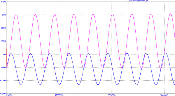
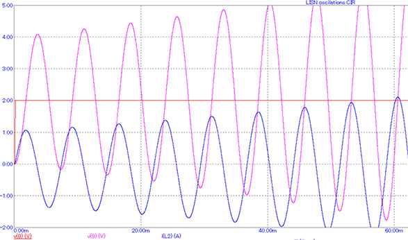
After switch “SW” turns on (or other change/step is introduced into the circuit), harmonic oscillations with frequency “fr” appear in this LC circuit.
fr = (1/2pi) * (1/sqrt(L*C))
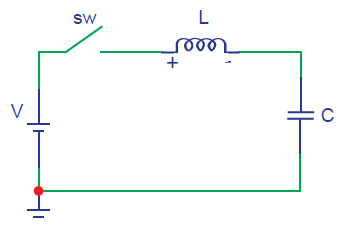
Because there isn’t dumping element dissipating the energy moving from magnetic field of the choke to electric field of capacitor and back, the oscillations of capacitor voltage and choke current continue forever with constant amplitude.
Theoretical Explanation (2/4)
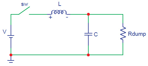
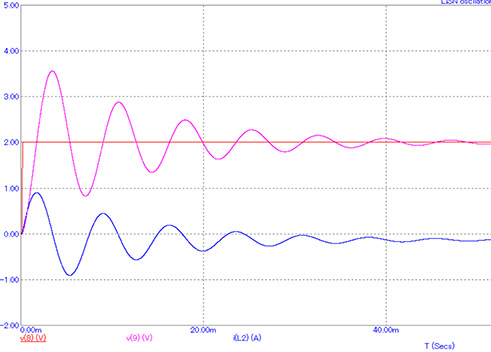
Once a dissipating element (resistor “Rdump”) is connected in the circuit, then the energy transfer between choke and capacitor has losses and amplitudes of oscillations do decrease in time.
Theoretical Explanation (3/4)
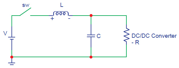
If there is regulated power converter connected instead of dumping resistor (load), then amplitudes are not dumped but are amplified in time.
This is due to regulator of the converter is increasing its input current when its input voltage is sinking (in order to keep the power delivery constant).
This can be represented with virtual term negative impedance / resistance and has opposite effect compared to dumping resistor (negative resistance supplies the energy into resonant circuit).
-R = dv/di = (Vin1-Vin2) / (Iin1-Iin2) = (Vin1-Vin2) / (P/Vin1 – P/Vin2)
Where P is input power of the converter.
Theoretical Explanation (4/4)
To compensate this effect at least equal dumping resistor “R” needs to be added to the circuit. In order to get adequate dumping, the value of “R” should be fairly low.
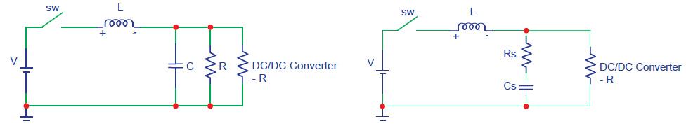
Parallel connection of dumping resistor “R” would cause additional significant dissipations at DC conditions. Therefore, it is better to use serial connection of resistor “Rs” and capacitor “Cs” to damp the oscillations more efficiently.
Available Solutions For Mitigating Oscillations During Surge Testing
| SOLUTION | ADVANTAGES | DISADVANTAGES |
| Series combination of damping resistor with capacitor |
|
|
| Input capacitor |
|
|
| Limit the bandwidth of converter regulation loop |
|
|
Explore Bel's Variety of Railway Solutions
With a global presence and decades of experience to leverage, the railway industry has come to rely on Bel as a stable partner in delivering railway solutions to transport the world.