RF Interconnect for the Next Generation of Phased Array Radar and Communications
Design considerations and connector solutions associated with building the next generation of phased array radar.
Download PDFThe latest phased array radar and communications systems being developed for Actively Electronically Scanned Array (AESA), 5G and Tactical communications are following trends of higher frequency operation and physical densification. With greater numbers of antenna elements, transmit/receive modules, antenna processors, and other analog/hybrid/digital beamforming modules in a single phased array antenna system, additional RF interconnect design considerations emerge. These new designs involve fitting a greater number of RF connectors and cable assemblies that also house more integrated PCBs that support analog, digital, and RF circuits. Reducing the size, weight, cost, and installation complexity of RF interconnects must also be considered.
This article aims to educate engineers and industry professionals working with phased array antenna systems for radar and the new design considerations and solutions that help mitigate the challenges associated with building the next generation of phased array radar.
Phased Array Radar Trends
Phased array antennas, and subsequent radar and communication systems, benefit from the physics of electromagnetics, in that the size of optimized RF structures is inversely proportional to the frequency at which they operate. This means that antennas built for higher frequencies are smaller and otherwise more compact than antennas for lower-frequency applications. In the case of multi-element antennas, such as phased array antennas, this means that increasing the operating frequency has a dramatic impact on the size, weight, cost, and even power of these systems.
RF Losses and Attenuation
There is a caveat, however, in that a variety of losses, such as RF loss and atmospheric attenuation, are also greater at higher frequencies. These additional losses can be compensated for by adding additional antenna elements in phased array radars. Moreover, incorporating active phase and amplitude control enables an operator or algorithm to precisely control the antenna pattern of a phased array antenna. In the case of AESA radars, jammers, and Tactical Communications, this ability is critical in avoiding harm to sensitive receivers, or more effectively controlling beam patterns to target enemy radar or friendly communications. This ability has given rise to a variety of actively controlled antenna techniques that allow for low-probability of intercept/low-probability of detection (LPI/LPD).
Johnson RF Interconnect Solutions
Discover the PossibilitiesMillimeter-wave Phased Array Antennas
Moreover, at higher frequencies, the beam width of an antenna becomes more narrow, enhancing the directivity over a comparable, but lower-frequency, multi-element antenna. These factors have given rise to the interest in using millimeter-wave (mmWave) phased array antennas for radars, jammers, Tactical Communications, and upcoming mmWave 5G communications. Though the compact nature of mmWave antennas becomes attractive from a size, weight, power, and cost (SWAP-C) perspective, the reduction in overall antenna size, alongside the dramatic increase in antenna elements, means that the associated RF interconnect must also be contained within these reduced-size modules. High-density RF interconnect, which still meet stringent MIL-SPEC ruggedness requirements, are necessary to provide the interconnect between the growing diversity of transmit/receive (TR) modules, Antenna Processing Units (APUs), hybrid-beamforming circuitry, and/or analog beamforming components.
High-quality RF interconnect that meet the SWAP-C requirements of these new phased array antenna systems is essential during the prototyping, testing, and production phases, and are also key components of deployed phased array systems. With the intended use cases of mmWave 5G extending to industrial, automotive, and infrastructure applications, it is likely that many of the same ruggedization and reliability requirements used by military/aerospace markets will extend to mmWave 5G.
Phased Array Radar Signal Chain
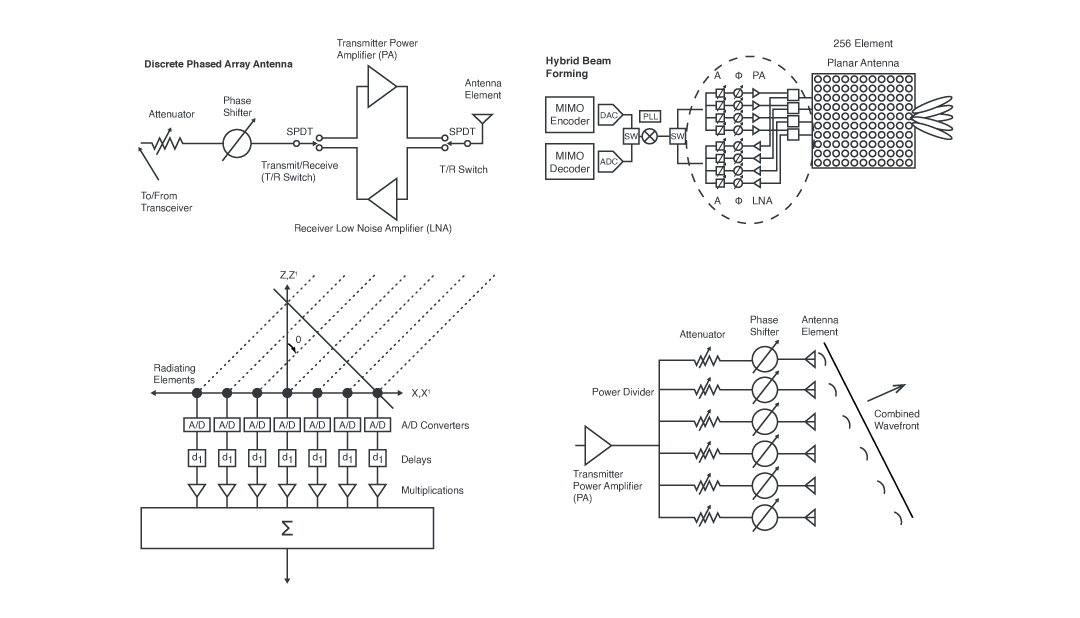
A basic phased array antenna consists of RF interconnect, attenuators/amplifiers, phase shifters, and antenna elements. In this basic case, RF interconnect is needed to connect between the transmitter, receiver, circulator/isolator/switch, attenuators/amplifier, phase shifter, and antenna elements. Another topology (that is becoming increasingly common) is the use of TR modules, which place the transmitter power amplifier (PA) and receiver low noise amplifier (LNA) in a module that is then connected through the same RF path to switches/circulators from the phase shifter to the antenna element. TR modules are used to enable the benefits of integration and modularity, further reducing the overall size of the antenna. This approach tends to require much smaller-pitch and higher-density RF interconnect than basic phased array antennas, as using larger RF interconnect negates many of the size and weight benefits of mmWave reduced element size.
The next level of this integration is to use hybrid, or digital, beamforming phased array antenna topologies that allow for much more compact components, such as System-on-Chip (SoC), System-in-package (SiP), integrated RF front-end modules, APU ASICs, and other types of compact assemblies, modules, or ICs. Hybrid and digital beamforming enable much more compact phased array antennas and can employ high-speed digital communications instead of RF communications between the modulation circuitry and the RF circuitry. In these cases, even tighter-pitch and higher-density RF interconnect are needed to provide connections between the high-speed communication buses of the modems and the beamforming electronics.
Though jammers and some lower-frequency radars will require larger-sized RF components and interconnect due to the power requirements of such systems, both Tactical Communications and mmWave 5G communications are likely to continue to greater levels of integration and densification. The need for this stems from reducing SWAP-C parameters and enabling the deployment of massive numbers of mmWave base stations, which would otherwise be limited if the SWAP-C parameters of the communication systems were comparable to radar and jammer systems.
The densification of mmWave phased array antenna systems also brings into consideration the sensitivity of such a system to external and internal interference, especially when considering the high-speed data lines and multitudes of low-power mmWave RF interconnect inevitable in communication systems. Coaxial cable assemblies and interconnect are excellent at providing shielded communications with minimizing insertion loss and attenuation. This concept also applies to highly sophisticated radar, which uses many of the same modulation technologies (spread spectrum) as modern communications. Hence, there is, and will be, a growing need for a wide range of high-density RF interconnect technologies, from ruggedized SMA cable assemblies to compact ultra-miniature ganged connector modules.
Figure 1.Discrete phased array (left) and hybrid beam forming (right) block diagrams.

RF Interconnect Design Considerations for Phased Array Antenna
Though radar, jamming, Tactical Communications, and mmWave 5G communications have very different end-goals and deployment scenarios, many of the RF interconnect considerations are the same. The following sections are dedicated to discussing the top design considerations for mmWave phased array antenna systems and include application-specific details and examples.
Phase Stability and Phase Matched Coaxial Cable Assemblies
The benefits of a phased array antenna are derived by the ability to precisely control the phase of the RF signal at the output of the antenna. This is only possible if the phase of the signal is stable and predictable throughout the phased array antenna system signal chain. There are two main RF interconnect considerations in this area. One is the phase stability of signals passing through a coaxial cable, based on environmental factors such as shock, vibration, flexure, warp, temperature, etc. Using “phase stable” coaxial cables helps to ensure that environmental influence is minimized.
The other consideration is the phase match between the coaxial cables used. Systematic phase error could be introduced by the coaxial cable production process, leading to even same-length coaxial cables exhibiting variances in the phase response. Hence, using phase-matched coaxial cables (which are cables ordered to have an incredibly similar phase response) can help to eliminate the concern of phase variances from RF interconnect and enhance predictability and performance of phased array antenna systems.
Mechanically Robust Connections
Military/aerospace manufacturers are required to use MIL-SPEC coaxial cables, connectors, and assemblies, which must meet a minimum standard of ruggedness and reliability. These standards include resilience to damage from shock, vibration, thermal cycles, and environmental agents. Especially with highly sensitive phased array antenna systems operating at mmWave frequencies, mechanical reliability is essential for all mission-critical RF communications, radar, and jamming. Even slight mechanical forces, if allowed to affect a phased array antenna system, could reduce overall system performance, produce hard-to-identify transient failures, or otherwise render the system inoperable.
Many of these high-reliability (Hi-Rel) standards also overlap with automotive and aviation standards, which will likely also impact upcoming mmWave 5G communication considerations. Therefore, for critical applications, such as industrial automation, automotive, and aviation, upcoming 5G systems may also be required to employ Hi-Rel coaxial interconnect or otherwise reliability-qualified coaxial interconnect.
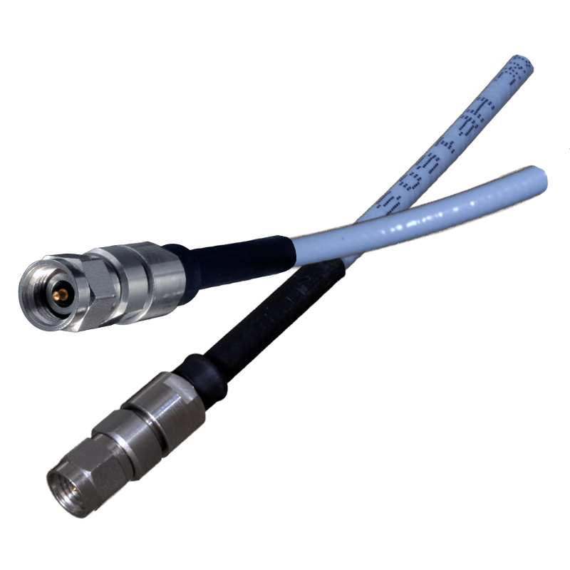
Image 1.Cinch JohnsonTM test cable assemblies.

mmWave Phased Array Connectors and Cables
Recent Tactical Communication and mmWave 5G communications are investigating using frequencies well beyond 18 GHz. At these frequencies, common RF coaxial interconnect (such as N-type, common SMA, SMB, etc.) are no longer viable due to the way electromagnetic waves traverse through coaxial structures. Therefore, physically smaller connectors are required for these new frequencies of interest, such as 2.92mm, 2.4mm, 1.85mm, high-frequency SMA, SMP, and SMPM, such as from Cinch’s Johnson™. The same concept applies to coaxial cables as well, as the size of the coaxial transmission line also determines the upper frequency at which a transverse electromagnetic (TEM) mode can be maintained. Conversely, the size of a coaxial connector and cable also influences the path loss, power handling, and mechanical strength of a coaxial cable assembly. Advanced materials and fabrication methods can be used to mitigate some of the negative performance effects of smaller coaxial transmission lines operating at mmWave frequencies.
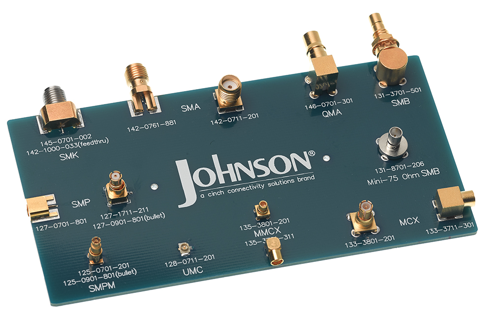
Figure 2.High-frequency Cinch Johnson™ connectors.

Image 2.Cinch Johnson™ sample board.

Johnson™ Connector Offering Across Frequency
| Connector Type | Frequency Range | Coupling | Family |
| 1.85 mm* | DC to 65 GHz | Threaded | Sub-miniature |
| SMPM / GPPO* | DC to 65 GHz | Snap On - Blind mate | Micro-miniature |
| 2.4 mm | DC to 50 GHz | Threaded | Sub-miniature |
| 2.92 mm / SMK* | DC to 40 GHz | Threaded | Sub-miniature |
| SMA / GPO* | DC to 40 GHz | Snap On - Blind mate | Micro-miniature |
| SMA | DC to 18 / 26.5 GHz | Threaded | Sub-miniature |
| KqiQMAte / QMA | DC to 12.4 GHz | Snap On | Sub-miniature |
| Type N | DC to 11 GHz | Threaded | Standard |
| SMC | DC to 10 GHz | Threaded | Sub-miniature |
| MCX | DC to 6 GHz | Snap On | Sub-miniature |
| MMCX | DC to 6 GHz | Snap On | Micro-miniature |
| UMX / u.FL | DC to 6 GHz | Snap On - Insertion Tool | Ultra-miniature |
| SMB | DC to 4 GHz | Snap On | Sub-miniature |
| SMB - Mini - 75 Ohm | DC to 2 GHz | Snap On | Sub-miniature |
Low-Profile and Tight-Pitch Interconnect
mmWave coaxial connectors’ smaller physical dimensions enable higher-frequency operation and much higher-density interconnect. Where larger coaxial connectors require threaded bodies for good mechanical/electrical contact, smaller connectors can benefit from slide-on/snap-on interfacing. This factor removes the need for extra pitch distances to be maintained for nut-tightening tools, such as torque wrenches, and allows for much more rapid assembly/disassembly and troubleshooting. Blind-mate connectors also can help reduce axial and radial misalignment issues, which are common with compact and dense interconnect scenarios. Moreover, these types of connectors can also be integrated into a multi-connector, or ganged, configuration, which allows for Blind-mate connectivity of multiple connectors simultaneously, like the SMP, Ganged 4 port SMP and SMPM solutions from Cinch’s Johnson™. These ganged connectors can greatly reduce the overall pitch of several similar connectors, simplify assembly, reduce BOM complexity, and even be used for board-to-board interconnect.
Figure 3.Cinch JohnsonTM mmWave connectors.

High-Density Board-to-board and Component-to-board Interconnect
Many prototype and future phased array antenna systems are leveraging greater levels of integration, which entails the use of PCBs and surface-mounted components. Using PCBs instead of connectorized assemblies limits the amount of space on a phased array antenna module for connectors, necessitating coaxial connectors capable of smaller pitches, surface mount connectors, ganged connectors, and even highly dense mezzanine style and stacking connectors. For board-to-board and component-to-board interconnect, an end-launch or surface-mount RF connector enables a tighter spacing of boards and components, and it reduces the RF path loss associated with unnecessary interconnect lengths.
While it is acceptable to solder end-launch or surface-mount RF connectors in many cases, there are some situations where this proves logistically difficult (or impossible). In extremely high-density interconnect (common with high-speed digital and complex hybrid/digital beamforming antenna systems), having to account for hundreds (or even thousands) of solder points could lead to manufacturing and quality challenges. Traditional RF board-mount and component interconnect requires soldering or weld bonding.
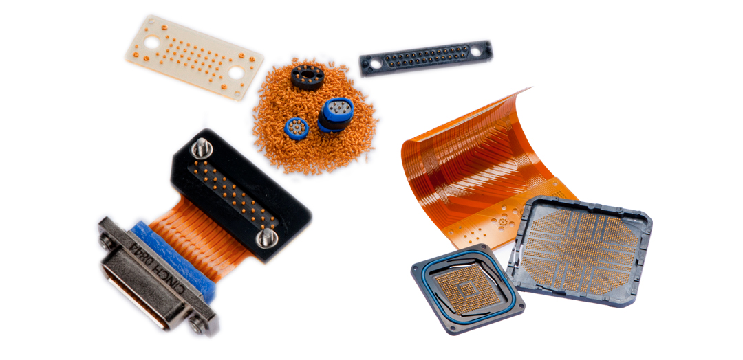
Fortunately, there are solderless surface mount connectors that use compressive force to establish a reliable and strong mechanical and electrical connection for board-to-board and component-to-board connections. For example, Cinch’s CIN::APSE® stacking connectors can be used for rigid-to-flex or rigid-to-rigid mezzanine stack PCB configurations with several to tens of contacts. This type of interconnect can be used in place of a multitude of individual connectors and can reduce the RF path, interference, interconnect failure modes, and installation failure modes while enhancing overall reliability and simplifying testing jigs.
Image 3.CIN::APSE® compression interconnects

Supply Challenges
In many cases, sourcing RF interconnect for a phased array antenna system could involve hundreds of vendors and turn-around times to keep track off. With military applications, as well as automotive and industrial, sourcing RF interconnect requires careful consideration. In many cases, a vendor may supply only a few components, but as much work is required to source from that vendor as one that supplies a larger variety of parts for the project. Moreover, military/aerospace applications, as part of MIL-SPEC, require a specific approach to materials and part sourcing that enforces quality control features as well as material and part sourcing functions. Therefore, it can benefit a manufacturer to work with a supplier that is familiar sourcing to military/aerospace customers with well-established MIL-SPEC-qualified manufacturing facilities, as well as being helpful for upcoming 5G mmWave automotive and industrial systems that may require similar qualification processes.
Next Generation of Phased Array Radar and Communications
Upcoming Millimeter-wave AESA radar, jammers, Tactical Communications, and even mmWave 5G systems are likely to rely on high-performance phased array antenna systems. This type of antenna introduces many layers of complexity to already sophisticated RF and digital systems, including vast additions to the RF interconnect in terms of a multitude of signal paths and components. These new applications require a much smaller pitch, and various matching-style RF interconnects beyond the traditional threaded coaxial connector. As military, aerospace, automotive, industrial, and consumer communications continue to advance and increase in frequency, so will the need for innovative RF interconnect, especially as integration trends accelerate and the lines blur between digital, analog, and RF device.

View Cinch's Full Line of Johnson RF Solutions
Learn More