
How Edge-Plating Improves Reliability of Attenuators
Discover how Bel’s innovative gold edge wrapping enhances reliability by improving a QPL attenuator’s ability to withstand mechanical shock and vibration.
Download PDFIn RF systems, attenuators are an essential building block. They are used to lower the level, and hence the power, of a signal by a pre-determined amount. This can be used to improve impedance matching, to protect sensitive equipment such as measuring devices from excessively high inputs that might cause damage, and to increase the reliability and quality of critical systems.
WHAT IS AN ATTENUATOR?
There are several different types of RF attenuator: they can be of a fixed attenuation value, can be switched between a set of values, or be continuously variable. The degree of attenuation is measured in decibels (dB) – for example, a 3dB attenuator reduces the output power to half of the input power, while 10 dB reduces the signal to a tenth the input power.
For many applications, fixed attenuators with specific values are often the simplest and best solution. These attenuators are passive devices which are typically constructed from three resistors, usually arranged in a ‘T’ or ‘Pi’ format (see Figure 1). The resistor values needed can easily be calculated from the required attenuation, and manufacturers typically offer parts in a wide range of attenuation values.
Figure 1. Diagram of T and Pi formats
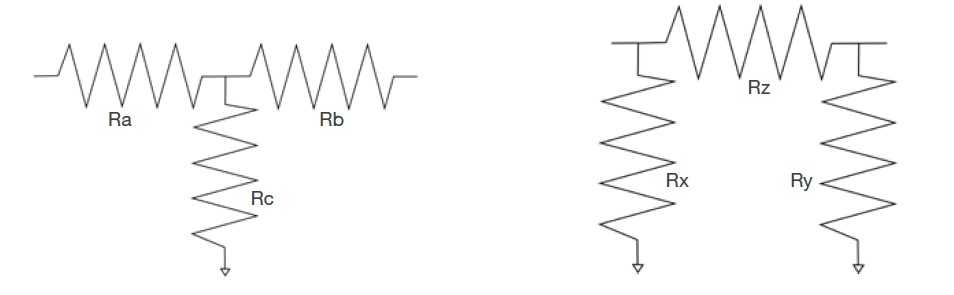
For RF applications, attenuators are often designed to be used in a system with 50 Ohms impedance, and can handle high frequencies up to 40GHz (typical). They can be constructed to be unbalanced for use with unbalanced coaxial lines, which are commonly used in RF applications, or alternatively can be balanced to use with twisted pair cables.
RF Interconnect for Phased Array Radar
See What's NewMEETING DLA QUALITY DEMANDS
To ensure the right levels of quality and reliability, across many different types of products, the USA’s Defense Logistics Agency (DLA) created what is called a Qualified Parts List (QPL). The DLA specifies the minimum performance requirements for the attenuators it purchases, which are then listed on the QPL, and this is seen as a general symbol of quality for other buyers. For RF and microwave fixed attenuators, the relevant specification is called MIL-DTL- 3933M and is available for download from the Defense Logistics Agency website.
The specification includes three device-level designators to use in part numbers:
- ‘T’ indicates a part for use in space applications
- ‘S’ shows the part has been screened
- ‘N’ designates non-screened parts
To be awarded QPL status, a manufacturer has to define tests for their parts that follow the specification, and then provide a detailed test report for review by the DLA. This means that customers can be confident that whoever they buy their attenuators from, they will meet an appropriate minimum standard for performance and quality.
RELIABILITY CONCERNS FOR FIXED ATTENUATORS
In practice, however, not all QPL parts are the same, and the specification doesn’t define how the parts are designed internally. A fixed attenuator is basically three resistors connected on a small circuit board, and provided in a suitable housing. One area that can greatly affect reliability is how the board is connected with the attenuator’s external connector – for example, the SMA (SubMiniature version A) coaxial connectors used in many applications.
Figure 2. A Midwest Microwave QPL attenuator
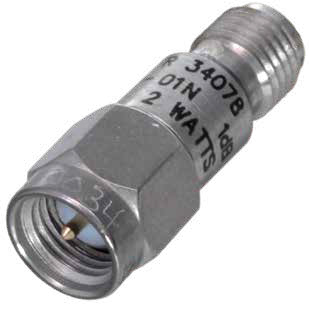
The circuit board has connectors on the side to route the signal to the SMA connector. Traditionally, the most common way to do this was to use a conductive area of epoxy, but this has several problems.
Firstly, the epoxy needs to be applied manually, which can introduce errors. Secondly, the epoxy is a chemical, and for some applications, ‘outgassing’ is an issue – which means that in a vacuum, some of the epoxy will come out and can cause problems. This is typically an issue for space applications.
One alternative to epoxy is to use soldering, but this also introduces the potential for errors and mis-applied solder.
BENEFITS OF EDGE WRAPPING
1. EDGE WRAPPING OFFERS HIGH QUALITY
To solve these issues, Cinch has invested in developing a new way of linking to the SMA connectors, which increases their reliability. This is based on a gold edge wrapping technique, which means the contact between the two parts is gold on gold, and that a good contact is ensured by a simple, mechanical spring-loaded force.
The shift to gold edge wrapping also required the mechanical redesign of the resistor circuit board, to ensure the components of the attenuator fit together appropriately.
The gold edge wrapping helps ensure high reliability, and specifically improves the attenuator’s ability to withstand mechanical shock and vibration. It can also help improve the reliability in relation to thermal shock and thermal cycling, where the attenuator may be frequently exposed to large changes in temperature, for example, in outdoor usage.
Since introducing this technique for its QPL attenuators, Cinch has had zero failures for these parts and is a pioneering manufacturer by using gold edge wrapping in this way for attenuators.
2. EDGE WRAPPING LOWERS COSTS
By improving reliability and avoiding failures, the new manufacturing technique also contributes to lower costs for customers. As well as the expense of the attenuator itself, which is relatively low, any problems in real-world usage could have substantial consequential costs – and many RF applications may be in remote places, where replacement of a part is far from simple.
3. EDGE WRAPPING ELIMINATES OUTGASSING
It also means that with a simple metal-to-metal contact, and no epoxy or solder, there is no outgassing, which can be essential for space applications and vacuum environments. For outgassing, there are two specifications of interest that should be considered when specifying parts. Firstly, look at TML, which stands for ‘total mass loss’. Secondly, you should consider CVCM, which means ‘collected volatile condensable materials’.
CINCH'S APPROACH TO EDGE WRAPPING
To give some examples, the new technique is used by Cinch in its line of QPL attenuators from Midwest Microwave, as well as in most custom attenuators developed by the company for various military programs. These parts exhibit low VSWR (Voltage Standing Wave Ratio), thus avoiding unwanted reflections, and high accuracy attenuation. They can be used over an extended temperature range of -55°C to +125°C, and are rugged in construction.
The new technique could also be used by Cinch to develop custom attenuators for customers where reliability is required, even where a QPL part is not needed. In fact, QPL is just the start – many non-defense applications could benefit from specifying this approach. In addition to attenuators, Cinch has also used gold edge wrapping to improve the reliability of terminations.
EXPANDING RELIABILITY BEYOND QPL
While they all meet the relevant specification, not all QPL parts are the same, and in particular the internal construction can vary. For attenuators, reliability is a key issue. Cinch has addressed this by developing a high-quality manufacturing technique that uses gold edge wrapping to make connections. This technique has proven its value in production – with a zero failure rate of Cinch’s QPL attenuators
View Midwest Microwave Full Line of RF Coax Attenuators
Learn More